K40 Laser HV Power Driver
As the investigation of the laser drive methods continues we now aspire to understand how HV power is applied to the K40 laser tube.This post is a continuation of laser-power-supply-control-take-2.html, Whereas the focus in that post was the understanding and implementation of digital controls, this post continues with a focus on understanding the internal driver circuitry of the LPS.
Other related posts are:
- http://donsthings.blogspot.com/2017/04/adding-analog-milliamp-meter-to-k40.html
- http://donsthings.blogspot.com/2017/01/k40-lps-configuration-and-wiring.html
- http://donsthings.blogspot.com/2017/01/k40-lps-repair-and-test.html
Contributors:
+Don Kleinschnitz
Donate:
Please consider donating (button to the right of this post).Your donations help fund additional research, tools and parts that I will return to the community as information.
For other information on the K40-S build use the K40-S BUILD INDEX with schematic
Don't believe me? Here is an example of the LPS's energy!
Video by +David Cantrell
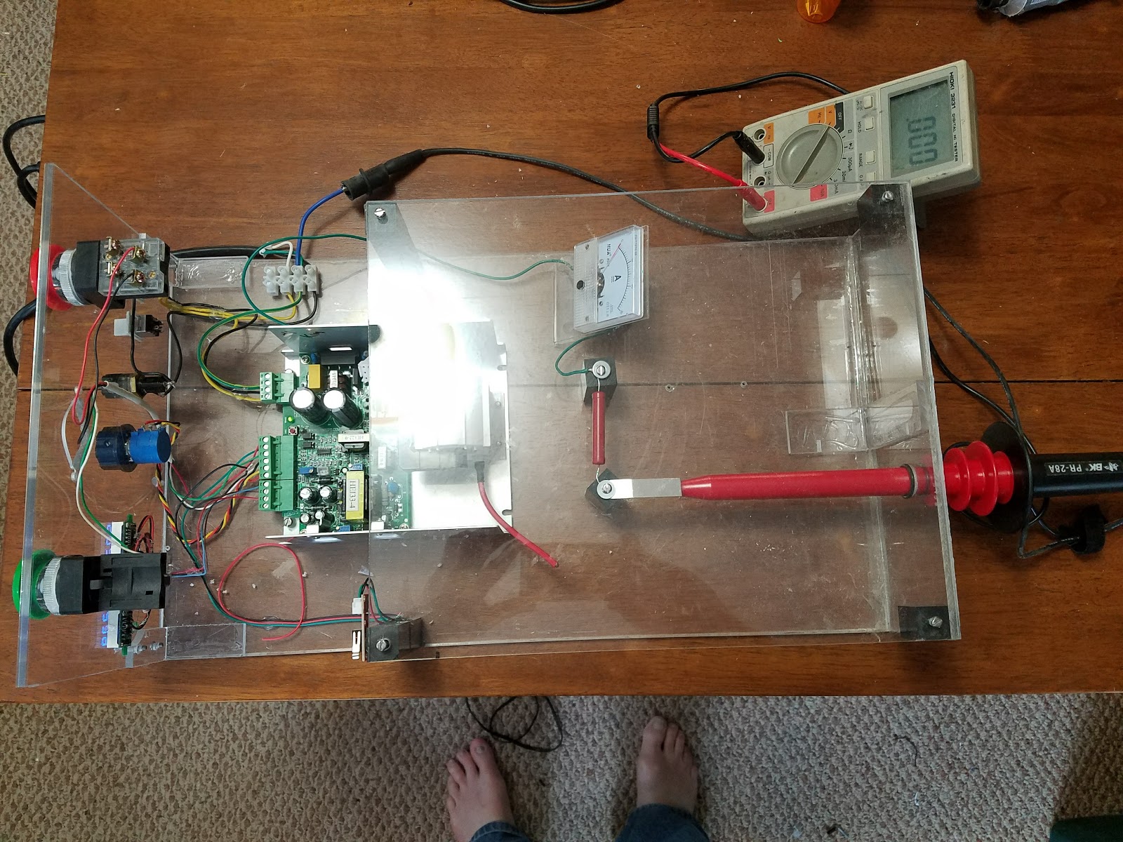
Most people are not skilled enough to be even near and certainly not inside a high voltage power supply such as this without special training and equipment. As an example, this is the specially designed and built lab environment that I use to work on Laser Power Supplies. Nothing less is acceptable.
Hopefully, there is enough information on my blog to satiate your curiosity about your LPS or help you troubleshoot outside of the LPS's guts.
The output of these supplies is a lethal 20,000 Volts but there are equally lethal voltages that can be found in the driver circuits (400 volts). This means that even if you disconnect the fly-back (where the highest voltage is created) lethal and high voltages are present in the voltage multiplier circuits.
These high voltages can also damage test equipment such as meters and oscilloscopes if grounding and input attenuation are not carefully planned.


An example HV diode specification.
Enjoy and comment
Maker Don
Warning
DON"T IGNORE THIS!
WARNING: LASERS AND THEIR HIGH VOLTAGE SUPPLIES ARE BOTH ELECTRICALLY LETHAL AND OPTICALLY DANGEROUS. THEY HAVE THE POTENTIAL TO KILL AND/OR BLIND YOU!
YOU ARE ENTERING A ZONE WHERE 20,000 Volts will be present!
- STAY FAR AWAY FROM THE HIGH VOLTAGE SUPPLY'S OUTPUT!
- WEAR PROTECTIVE EYE-WARE AT ALL TIMES WHEN OPERATING A K40!
- DO NOT OPERATE A K40 WITHOUT THE PROPER LASER INHIBITING INTERLOCKS INSTALLED AND OPERATING PROPERLY!
- USE THE CORRECT HIGH VOLTAGE SAFETY PROCEDURES
IN READING THIS POST YOU AGREE TO USE THIS INFORMATION AT YOUR OWN RISK!
I DO NOT RECOMMEND THAT YOU OPEN, PROBE, REPAIR OR OTHERWISE ACCESS THE INTERNALS OF A LASER POWER SUPPLY. YOU PROCEED FROM HERE AT YOUR OWN RISK!
Don't believe me? Here is an example of the LPS's energy!
Video by +David Cantrell
Safety
Hopefully, there is enough information on my blog to satiate your curiosity about your LPS or help you troubleshoot outside of the LPS's guts.
The output of these supplies is a lethal 20,000 Volts but there are equally lethal voltages that can be found in the driver circuits (400 volts). This means that even if you disconnect the fly-back (where the highest voltage is created) lethal and high voltages are present in the voltage multiplier circuits.
These high voltages can also damage test equipment such as meters and oscilloscopes if grounding and input attenuation are not carefully planned.


LPS Schematics
The updated schematic is used as the base for the "theoretical" theory of operation given below.
The embedded schematic below .....
https://www.digikey.com/schemeit/project/k40-lps-2-EFKO7C8303M0
The embedded schematic below .....
https://www.digikey.com/schemeit/project/k40-lps-2-EFKO7C8303M0
PWM control
Much of the PWM's operation was covered in the related post so it is not repeated here.
HSwitch
The output of the PWM drives, with a complementary signal, an Hswitch which in turn drives a transformer in a push-pull fashion. The secondary of this transformer drives the HV driver MOSFETs.Charge/Voltage Doubler
The charge (voltage) that is dumped through the HV HVT is created using a doubler technique. Each of the doubler capacitors it charged respectively on each 1/2 cycle of the input AC through the full-wave bridge. This results in 2x the input voltage on the series combination of the two capacitors.
This reference is what helped me decode this circuit: PowerSourcesForCW-Lasers
This reference is what helped me decode this circuit: PowerSourcesForCW-Lasers
AC Line Voltage selection
There is a selection switch on these supplies for 115 and 240 volt operation. When the switch is in the 115 volt position only one of the capacitors is charged at time so the voltage across each is equal to the line voltage (115) and when in series they add to 2x line voltage (230).
When the switch is in the 230 volt position the capacitors are charged in series so each capacitor has 1/2 AC Volts or 115 volts each. The net result with 230 VAC in is the same as 115 VAC in.
The operation is simplified in the image below.
 |
| Voltage Doubler Operation |
HV Driver
The HV driver uses the complementary signal from the Hswitch to dump the charge from the doubler capacitors through the HVT's primary. This results in a secondary high voltage that is roughly proportional to the HVT's winding ratio * primary voltage.
The image below is a simplified view of its operation. It shows that the current is dumped through the HVT in two directions, creating an AC-like signal that has a period equal to the PWM. I need to verify this theory with a scope.
Open question: This method senses current in the HVT primary but how does that know and regulate the current in the tube. The tube exhibits a negative resistance when it fires so how is the current in the tube measured and regulated, seems it isn't.
The image below is a simplified view of its operation. It shows that the current is dumped through the HVT in two directions, creating an AC-like signal that has a period equal to the PWM. I need to verify this theory with a scope.
 |
| Simplified HVT Driver |
Sense Transformer
In series with the HVT and in turn, its current is a transformer that converts the HVT current to a proportional DC voltage. This voltage provides current (I) feedback to the PWM controller.Open question: This method senses current in the HVT primary but how does that know and regulate the current in the tube. The tube exhibits a negative resistance when it fires so how is the current in the tube measured and regulated, seems it isn't.
HVT Transformer
Most K40 HVT's (in the teardowns we have done) consists of a voltage doubler.
For more info on the HVT see these posts:
https://donsthings.blogspot.com/2017/06/k40-high-voltage-transformer-autopsy-2.html
https://donsthings.blogspot.com/2017/06/k40-flyback-autopsy.html
For more info on the HVT see these posts:
https://donsthings.blogspot.com/2017/06/k40-high-voltage-transformer-autopsy-2.html
https://donsthings.blogspot.com/2017/06/k40-flyback-autopsy.html
An example HV diode specification.
Enjoy and comment
Maker Don